Data structures in Jitterbit Integration Studio
Introduction
Data structures can be provided as schemas during activity configuration or they can be defined within the transformation itself. When data structures are provided in an activity, the schemas are inherited by the transformation using the activity as a source or target in the operation. Once the source and target schemas of a transformation are defined, you create transformation mappings between the source and target schemas to define how data should be processed.
For information on resolving certain operation execution errors caused by data structures, see Operation troubleshooting.
Data structure types
In Harmony, source and target schemas may use data structures that are considered to be either flat or hierarchical.
Flat structure
A flat data structure consists of one or more single fields and records in a two-dimensional structure. Examples include CSV files, simple XML files, and single database tables. A flat data structure is also referred to as a flat file structure.
<customer>
    <id>10123</id>
    <name>ABC Co.</name>
    <street>1 Main St.</street>
    <city>Anytown</city>
    <state>NY</state>
    <zip>12345</zip>
</customer>
Hierarchical structure
A hierarchical data structure has one or more parent-child or nested relationships between fields and records in a complex structure. A hierarchical data structure is sometimes referred to as a relational, multilevel, complex data, or tree structure.
<customer>
    <id>10123</id>
    <name>ABC Co.</name>
        <addresses>
            <address>
                <street>1 Main St.</street>
                <city>Anytown</city>
                <state>NY</state>
                <zip>12345</zip>
            </address>
            <address>
                <street>1 Time Square</street>
                <city>New York City</city>
                <state>NY</state>
                <zip>54321</zip>
            </address>
        </addresses>
</customer>
Display of data structures
Data structures are displayed in a tree format that can be expanded and collapsed to show either the entire tree or just a portion of it.
Each tree consists of nodes and fields, where fields within the source data structure can be mapped to fields within the target data structure.
Nodes have a disclosure triangle to the left of the node name that is used to collapse or expand the node. By default, nodes are expanded up to 8 levels deep for schemas with 750 or fewer nodes and up to 5 levels deep for schemas with more than 750 nodes. All nodes beneath a target node can be expanded at once using the schema actions menu option Expand all nodes beneath this node (see Target nodes in Mapping mode). If you expand or collapse nodes, Integration Studio remembers the last expansion state you were using the next time you access the transformation.
Once expanded, nodes display any contained child nodes and fields. Nodes can be considered as folders with child nodes as sub-folders. Fields are contained within nodes and are listed with their data type (boolean, integer, double, binary, string).
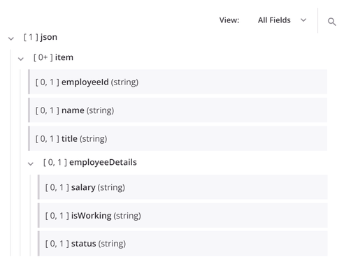
For example, in the target structure shown below, the node json includes the child node item, which contains the fields employeeId, name, and title. The node item also contains the child node employeeDetails, which contains the fields salary, isWorking, and status.
Display of mapped fields
A transformation mapping consists of target fields or nodes and their corresponding scripts. These scripts may contain references to source fields or nodes or to project components, use functions, or contain other valid script logic. A mapping does not include target fields that are not mapped.
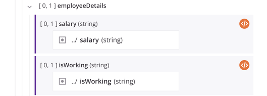
When source objects and variables are defined within the target field, they appear as blocks within the target field. The mapped target field is displayed with a purple vertical line along the left of the target field block:
When you are in mapping mode and both a source and a target schema are visible on the screen, a visual light gray line shows the connection with the source object when you hover on a source or target field.
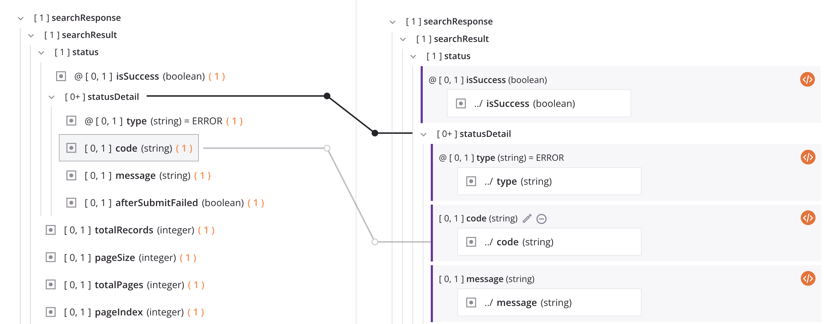
The solid black line shown in the above image is explained in the next section, Loop nodes.
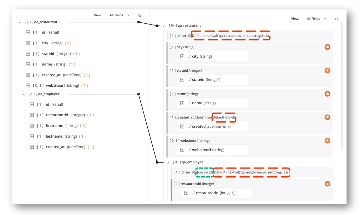
The target side of the mapping also indicates if a field has any default values (outlined in red in the image below) or joins (outlined in green in the image below). For example, this transformation inserts data into a database whose id fields are auto-incremented and whose created_at field is set equal to the current time by default. It also shows that the child table qa_employee has been joined on the id field to its parent table qa_restaurant:
If a collapsed node contains target field mappings, that node is shown in bold to indicate it contains mappings:

Loop nodes
A loop node is a source or target node with repeating data values, such as line items in an invoice or a set of customer records.
When loop node fields are mapped, a solid black iterator line automatically appears, indicating that the transformation process will loop through the source data set. The location of the generated iterator lines depends on the multiplicity of the corresponding source loop nodes.
A transformation can have zero or more iterator lines. When multiple iterator lines are present, precedence is given from top to bottom of the target structure.
To toggle the display of an individual iterator line, click directly on the circle shape that is closest to the target node:
![]()
The individual loop node line then becomes an orange stub that when clicked again displays the full line:

Example
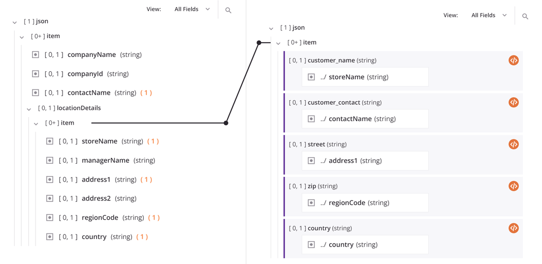
As an example of a loop node mapping, consider the following hierarchical source structure containing a top-level source node (item) with fields that provide information about a company. A child source node, locationDetails, includes an array (json$item.locationDetails$item.) of objects with fields for multiple store locations within a company. Both the parent and child node are considered loop nodes because the data may contain multiple company records with multiple store location records for each company.
Now consider that this data is being mapped to a flat target structure, resulting in a record for each store location. As you map fields, an iterator line automatically appears connecting source and target loop nodes. This line indicates that the target will loop as many times as there are repeating sets of data in the source, or in this example will loop through each store location record for each company.
Map from a multiple-instance source to single-instance target
When the generated target loop node depends on more than one source loop node, you may need to resolve an occurrence mismatch with the mapping.
If the source data structure is a multi-object array and is being mapped to a target data structure with a single object, this dialog is displayed:

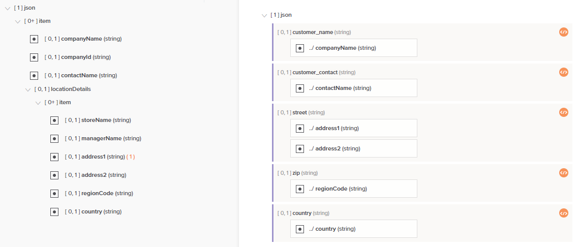
To use the first instance of the source in the mapping, select Yes to automatically insert a hash symbol (#) in the reference path of the data element. This means that only the first record will be mapped. For example, given the following mapping, only the first customer record in the array is mapped to the target structure containing only a single customer. Notice that each mapped target field now contains a script as indicated with the script icon.
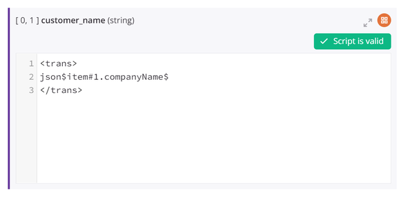
When you toggle to script mode for any mapped field, you will see that a #1 has been added within the path of the mapped source object to indicate that the first instance is mapped.
If you do not want the first instance of the source to be used, you can specify other logic using the instance-resolving functions (see Instance functions).
Data normalization
If you are mapping data from a flat structure to a hierarchical structure, the data may need to be normalized before being transformed.
By default, Harmony uses a normalization algorithm to construct the target tree. This will convert the flat structure of the source into a hierarchical source structure that can then be mapped to the hierarchical target structure.
In the target structure, the root element and all of the multiple-instance elements under the root are used to create the structure of secondary source elements. The attributes (or fields) of these secondary source elements are flat data elements that are then used in the mappings of the corresponding target element.
With the source structure properly defined, the normalization process is simplified to combining nodes with the same parents.
There are three options for normalization:
- Complete Normalization: All the elements with the same parent and all the fields are reduced to one element. (This is the default.)
- Partial Normalization: The same as complete normalization, except that the lowest children are not normalized.
- No Normalization: Each flat record creates a branch of elements; no reduction of elements is performed when creating the hierarchical source structure.
It is possible for the hierarchical structure to contain a single instance node. In that case, only the first element for this root will be kept, and flat records that conflict with this root data node will be ignored.
To disable normalization, set the Jitterbit variable jitterbit.transformation.disable_normalization to true (see Transformation Jitterbit variables).
Instance and multiple mapping
Transformation mapping is the process used to define the relationship of data between inputs and a resulting output of data. Depending on which data structure types are used, the transformation mapping may be described as instance mapping or multiple mapping.
Instance mapping
Instance mapping describes when the mapping of a target instance depends on possibly more than one instance of a source. Instance mapping can be either flat-to-flat (one-to-one) or hierarchical-to-flat (many-to-one).
Multiple mapping
Multiple mapping describes the mapping of two hierarchical data structures or the mapping from a single, flat structure that is actually hierarchical in nature, with its lower segments containing multiple sets of values such as name/value pairs. Multiple mapping can be either hierarchical-to-hierarchical (many-to-many) or flat-to-hierarchical (one-to-many).
Examples
Sample situations for both instance and multiple mapping can be found within the Design Studio documentation:
- Instance Mapping
- Multiple Mapping
Although these examples are for Design Studio, the same concepts can be applied in Integration Studio.
For hands-on training modules that have examples of mapping simple and complex database, text, and XML files, see Introduction to Jitterbit Integration Studio.