Key concepts for transformations in Jitterbit Studio
This page explains the core concepts to understand when you are designing transformations and troubleshooting issues.
Schemas
A schema defines the structure and data types of your input or output data. Schemas specify which fields are available, their data types, and how fields are organized:
Source schemas
The source schema describes the structure of data coming into your transformation. Source schemas can come from these sources:
-
Activity-generated schemas: Automatically created by connector activities like database queries or API calls.
-
User-defined schemas: Custom schemas you create or upload.
Source schemas are optional. You don’t need a source schema if you’re only using variables, custom values, or scripted logic in your mappings.
For more information, see Choose schema sources.
Target schemas
The target schema describes the structure of data leaving your transformation. Like source schemas, target schemas can be activity-generated or user-defined.
Target schemas are always required. Every transformation must have a target schema that defines the output structure.
For detailed guidance on creating and configuring schemas, see Create a transformation and configure schemas.
Data structures
Data structures define how information is organized within schemas.
Flat structures
Flat structures contain fields in a single level with no nesting. Examples include these formats:
- CSV files with columns
- Single database tables
- Simple XML files with no nested elements
Example
<customer>
    <id>10123</id>
    <fullname>ABC Co.</fullname>
    <street>1 Main St.</street>
    <city>Anytown</city>
    <state>NY</state>
    <zip>12345</zip>
</customer>
Hierarchical structures
Hierarchical structures contain nested relationships between fields and records. Examples include these formats:
- Complex XML files with nested elements
- JSON objects with nested properties
- Database joins across multiple tables
Example
<customer>
    <id>10123</id>
    <name>ABC Co.</name>
    <addresses>
        <address>
            <street>1 Main St.</street>
            <city>Anytown</city>
            <state>NY</state>
            <zip>12345</zip>
        </address>
        <address>
            <street>1 Time Square</street>
            <city>New York City</city>
            <state>NY</state>
            <zip>54321</zip>
        </address>
    </addresses>
</customer>
For more information about working with data structures, see Map data.
For complex hierarchical data scenarios, see Work with hierarchical data.
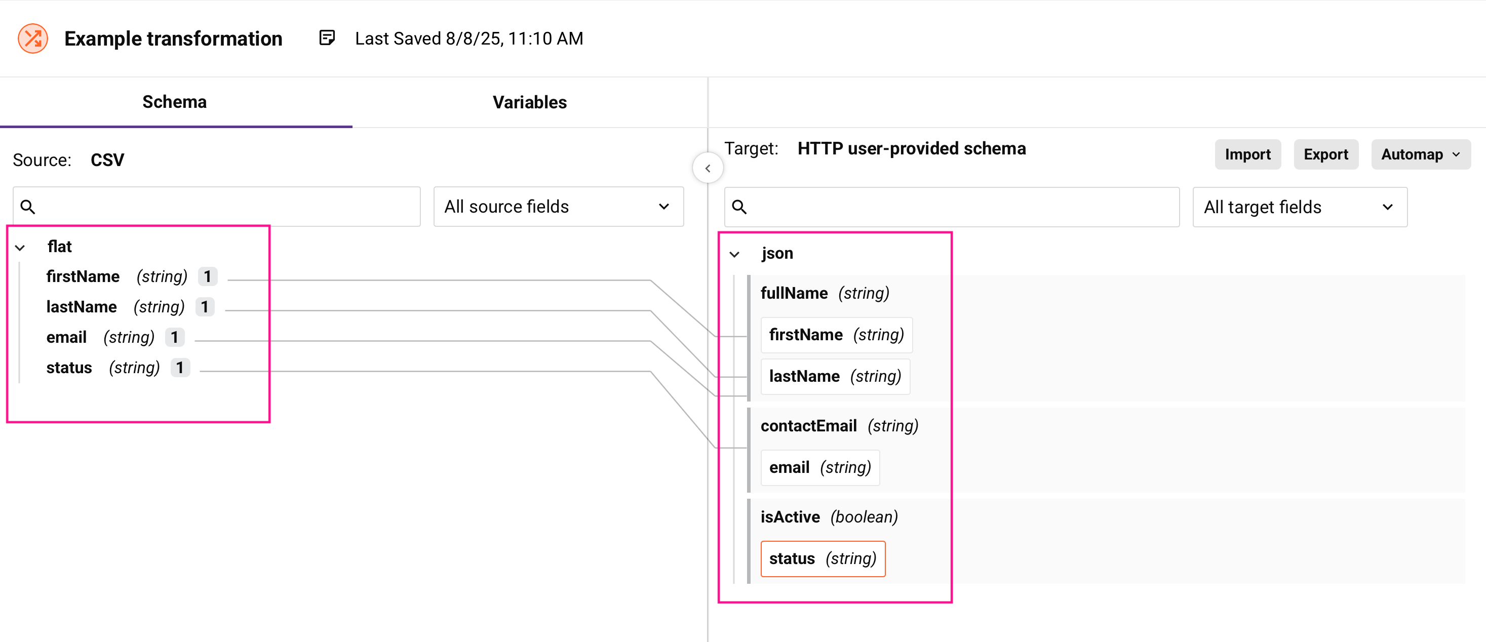
Nodes and fields
Schemas are displayed as tree structures containing nodes and fields. Nodes are containers that organize fields in hierarchical structures. Fields contain the actual data values.
Each node and field shows these visual indicators:

- Cardinality key: Shows occurrence rules in brackets.
- Name: The element identifier from the schema
- Data type: For fields only (string, integer, boolean, etc.)
-
Attribute/value indicators: Some XML structures include additional symbols:
Symbol Meaning @Element attribute data, for example @image#Element text data, for example #text
Nodes
Nodes are containers that organize fields in hierarchical structures:
- Carets: Expand and collapse nodes.
- Bold names: Indicate nodes containing mappings when collapsed.
- Default expansion: 8 levels deep for schemas fewer than 750 nodes, 5 levels deep for larger schemas.
You cannot map data directly to nodes. Instead, you map data to the fields that nodes contain.
Fields
Fields hold the actual data values and have these properties:
- Name: The field identifier.
- Data type: The data type, such as string, integer, boolean, date, and others.
- Format: Optional formatting for dates or currency.
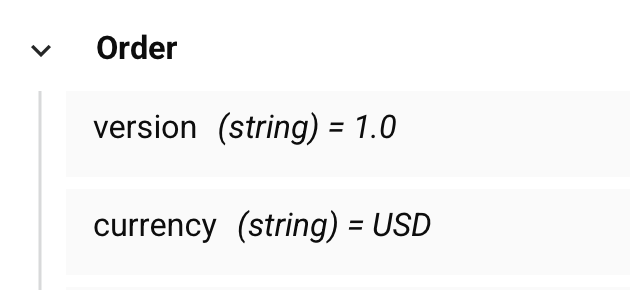
-
Default values: When an XSD or WSDL schema specifies a default value for an element or attribute, the value appears next to the field name in the transformation interface:
Cardinality notation
Cardinality keys indicate occurrence rules using UML-style notation:
| Cardinality key | Definition |
|---|---|
[1] |
Exactly one element (required) |
[1+] |
One or more elements (required, repeatable) |
[0,1] |
Zero or one element (optional) |
[0+] |
Zero or more elements (optional, repeatable) |
Mappings
A mapping connects source data to target fields and defines how data should be transformed.
Types of mappings
-
Direct field mappings: Connect source fields directly to target fields. See Map fields manually.
-
Custom value mappings: Assign static values or expressions. See Use custom values.
-
Variable mappings: Reference project or global variables. See Map variables.
-
Script mappings: Use functions and logic to transform data. See Mapping with scripts.
-
Conditional logic: Apply different logic based on conditions. See Conditional logic.
Mapping scripts
All mappings are implemented as scripts on target fields. Even visual mappings like drag-and-drop create underlying scripts. You can edit these scripts directly for complex transformations.
For automatic mapping of similar structures, see Map identical structures.
Loop nodes
Loop nodes handle repeating data, such as multiple records or arrays. When you map fields within loop nodes, the transformation processes each iteration of the data.
Automatic loop generation
Loop nodes are generated automatically when you map fields from repeating source data to repeating target structures. An iterator line appears that shows how the transformation will loop through the data.
Manual loop definition
You can manually define loop nodes when the automatic generation doesn't match your data processing needs. This is useful when you have multiple levels of repeating data and need to control which level drives the iteration.
For comprehensive guidance on working with repeating data, see Control data loops.
Variables
Variables are designed for passing values, configuration settings, and small amounts of data between different components in your integration. Variables are useful when you need to share information like session IDs, configuration parameters, or calculated values across scripts, transformations, and operations. These variable types are available for use:
| Type | Scope | Best for |
|---|---|---|
| Local | Single script | Calculations and temporary values |
| Global | Operation chain | Passing data between operations |
| Project | Entire project | Configuration and credentials |
| Jitterbit | System-defined | Runtime information |
For examples and detailed information about each variable type, see their individual documentation pages.
For practical examples of using variables in transformations, see Map variables.
Data flow
Data flows through transformations in this sequence:
-
Input: A source activity provides data matching the source schema.
-
Processing: A transformation applies mappings, functions, and business logic.
-
Output: The transformed data matching the target schema goes to the target activity.
Understanding this flow helps you design mappings that handle data correctly and troubleshoot issues when data doesn't transform as expected.
For validation and troubleshooting guidance, see Test and validate transformations and Resolve transformation mapping conflicts and errors.